After the sample
rate is chosen in Chart mode or Oscilloscope plus Cart mode, the program 'loops', one channel
at a time, through a series of windows that define the ACQUISITION PARAMETERS
specific to each channel. The panel at the top of the screen indicates
which channel is being defined at the moment. For each channel, select the following:
A
to D INPUT This links the 'logical' channel to a physical
connector to the analog-to-digital converter (UI2, DataTaker,
ADC-1, etc.). You can select any of the A to D channels that are available,
in any order; you may also assign a single hardware input to several logical
channels.
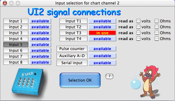
The A to D INPUT window looks more-or-less like this (the example is for the Sable UI2; the number
of available inputs and other options depend on the specific A-D converter in use).
Here, eight voltage inputs, four temperature inputs, and several other
inputs are available. One (temperature channel T3) has already been selected,
and the user has chosen voltage input 5 for channel 2.
Note: When using the ADC-1, you can set each channel to
automatically adjust the gain function to maximize resolution (the default
mode), or to use a fixed gain (of 1 or 50). The latter option is
slightly faster.
Streaming serial input
| A number of Sable
Systems instruments (and others) have serial ouputs; these send a fixed-format
string of digital data directly to the computer, avoiding the need for an A-D
converter. Usually, several different variables are sent. LabHelper
X knows the 'signatures' of some Sable instruments (the first
part of the string contains an instrument ID), and can parse the string
into the appropriate variables, with channel labels.
In the following example, from the Sable
RH-100 humidty sensor, the device provides humidity as percent
relative humidity, dew point, and vapor pressure; it also shows
internal temperature. You need to pick one of these variables to
record. It's also possible to adjust the Y-axis scale on the plot; LabHelper X will make a guess for these limits.
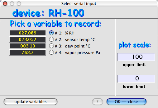
- (The 'update variables' button takes another reading from the
instrument and updates the data fields)
Note that most Sable serial instruments update their serial strings
only once or twice per second, so it's inadvisable
to use this option at high sampling rates. |
VOLTAGE CONVERSION This
defines the mathematical conversion that must be applied to the input voltage
to produce the desired units.
DISPLAY SCALING This
sets the Y-axis scaling for the computer's stripchart or oscilloscope display.
SAMPLE AVERAGING This
sets the method and number of samples to be averaged for each recorded data
point.
Once all these values have been defined for the various channels, the
acquisition parameters can be saved in a 'setup' file for later use.
This enables you to use the same sampling parameters without having to redefine
them every time the program is run. Setup files are saved from the
OPTIONS window, or by using the  M keyboard command (not available from certain windows). M keyboard command (not available from certain windows).
|
 Warthog Systems LabHelper X