|
Sable Systems makes a very nice 8-channel
multiplexer to switch airflows (4-channel versions have also been produced). These work quite well with
the LabHelper software, but for maximal effectiveness there are a
few points to keep in mind:
Because
the Sable unit is controlled with 3-bit word coding, only one of its devices
(solenoid valves) can be switched on at a given time. Thus you might
expect that you could only monitor one animal at a time even if you have
more than one analyzer available. However, the design of the Sable
multiplexer is quite clever: each solenoid switches TWO
air streams. There are 8 connectors that are switched through the
'IN' port, and another 8 connectors that are switched through the
'OUT' port (these labels may differ on units of different vintage). These two sets of plumbing are independent of each other
(except that a given valve's IN and OUT connections are both activated or
deactivated simultaneously). Therefore...... you can sample
from two respirometry chambers simultaneously as long as
both are attached to the same solenoid (valve) on the multiplexer (one to the
IN port and one to the OUT port).
It's
quite straightforward to connect just two animals, since a given analyzer
will only be recording data from one of them (or a reference). But
why have an 8 (or rather, 16) channel multiplexer if you can only do 2 animals
at a time? In theory, you could connect up to 14 animals and 2 references
air streams and, in periodic references mode, sequentially sample
from them two at a time. This has the potential for creating serious
confusion during data analysis unless you take steps to insure that LabHelper
records data only for channels that are actually being sampled by the analyzer.
In 'one line per device' mode, LabHelper switches the two valves
independently and each channel is associated with a different valve,
so it knows which channels are active and which are not. It can then
enter values of zero into channels that are not being sampled at a particular
time. However, when using the Sable multiplexer with two channels
connected through a SINGLE valve, LabHelper has no direct way of
automatically identifying the SECOND channel associated that valve.
You need to provide this information using the zero linking option.
Click the 'extra zero linking' button, and when you exit the EXTERNAL
DEVICE CONTROL window, the program will open a window showing the directly
switched channels. Click the appropriate 'additional channel'
buttons to 'zero link' other channels.
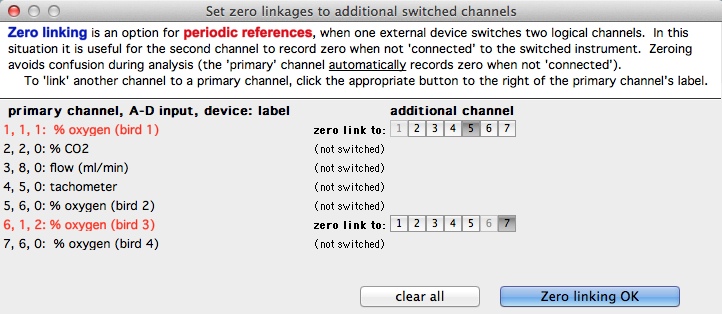
In this example, there are seven data channels. Four of these (#s
1, 5, 6, and 7) record oxygen consumption of different birds.
A dual-channel oxygen analyzer is in use, so we can measure two birds simultaneously.
Note that the hardware A-D inputs for the two 'halves' of the analyzer
are 1 (connected to data channels 1 and 6) and 6 (connected
to data channels 5 and 7). Finally, two valves are in
use. Valve 1 handles airflow from birds 1 and 2 (i.e., data
channels 1 and 5). Valve 2 handles airflow from birds 3 and
4 (i.e., data channels 6 and 7).
The primary data channels (in other words, the ones LabHelper
knows are linked to valves) are 1 and 6. When the program switches
from Valve 1 to Valve 2, it automatically zeroes channel 1 and activates
channel 6. But without further input it does not know that Valve 1
also switches data channel 5 and Valve 2 also switches data channel 7.
When valve 1 is on, the oxygen analyzer is reading gas streams from birds
1 (via one sensor) and 2 (via the other sensor). When valve 2 is on,
the analyzer is reading gas streams from birds 3 (via one sensor) and 4
(via the other sensor). Thus when valve 1 is on, both data
channels 6 and 7 should be set to zero. Similarly, when valve 2 is
on, both data channels 1 and 5 should be set to zero. This
is indicated by selecting the appropriate buttons in the "additional
channel" rows.
Cable connections The
multiplexer (and other Sable solenoid valve devices) expect their
control signals to be coded in "3-bit word" mode, not "one
line per device" mode. Select this option in the top right corner
of the EXTERNAL DEVICE CONTROL window. You may also need to make
sure the wiring is correct. The Sable unit comes with a connecting
cable terminating in the appropriate multi-pin connectors that fit the Sable UI-2 and the multiplexer. Earlier versions had a cable with a multi-pin connector at one end (plugging into the multiplexer) and several color-coded wires at the other end. These wires correspond to particular
bits in the 3-bit coding scheme (along with a digital ground wire).
Make sure these are connected to the appropriate outputs from your A to
D device:
- For the Sable UI-2: New-production multiplexers are shipped with a double-ended cable that plugs into both the UI-2 and the multiplexer.
Older versions came with a single-ended cable with bare wires on one end. Connect the wires to the corresponding outputs on the small 'daughter board' that comes with the main UI-2 unit.
Find the connector handling the lowest bit (bit 0) on the Sable daughterboard and connect
it to bit 0 on the multiplexer, and do the same for the other wires.
Then connect the Sable daughterboard's digital ground to the digital ground on the multiplexer. [All this may seem complicated,
but you only have to do it once.]
- For the ADC-1 and DataTaker, You'll have to modify the double-ended cable that comes with new-production multiplexers, or add a 'converter' to the end that doesn't fit directly into the multiplexer. Then perform the same operation describe above.
In other words, find the connectors for the digital outputs on the A-D
device, using the instruction manual. Then connect the Sable's bit
0 wire to the lowest-numbered connector on the A-D device, and so forth.
|
 Warthog Systems LabHelper X