|
If you are unfamiliar with the fundamentals of respirometry, you might want to read this page before diving into the rest of this section. Also, John Lighton's book, Measuring Metabolic Rates - A Manual for Scientists is an excellent in-depth reference.
|
This page covers 'constant flow' (or 'open sytem') respirometry, where a respiratory fluid -- typically air or water -- is flowed past the animal while excurrent gas concentrations are continuously monitored. Most of the discussion concerns systems for air-breathing animals. For the alternate method of 'constant volume' (or 'closed system') respirometry, see this page.
|
When thinking about setting up an open system, perhaps the key issue is the 'plumbing' that connects the various parts of the system. These are:
- The source of air (or other gas): positive-pressure (a 'push' system), or negative pressure (a 'pull' system). In positive-pressure systems, the gas source is upstream from the animal chamber, while in negative-pressure systems it is downstream from the chamber.
- Where the flow rate is measured (upstream or downstream from the chamber).
- A related question is how much flow is appropriate. This depends on the size of the animal (and hence its metabolic rate), the sensitivity of the gas analyzers, and other factors such as chamber volume and the necessity to rapidly detect changes in metabolism. The 'Minimum flowrate' section of the metabolism calculator in the SPECIAL menu can provide an estimate of the required flowrate for a range of animal taxa.
- Whether -- and where -- the gas stream is 'scrubbed' of components such as water vapor or CO2 with desiccants, CO2 absorbants or (for water vapor) 'freeze loops'.
- The type and arrangement (sequence) of different gas analyzers (e.g., for O2, CO2, and water vapor).
- Whether or not the excurrent gas stream (i.e., downstream from the animal chamber) is subsampled prior to analysis. Subsampling diverts a small fraction (e.g., 50-150 ml/min) of a much larger airflow into the analysis instruments. Subsampling is usually necessary or appropriate for large animals with high gas flow rates, but perhaps not for small animals with low flow rates. This is because some analyzers do not 'like' high flows, and because subsampling will likely reduce the consumption rate of scrubber chemicals. Even for low flow rate systems, subsampling is often helpful or mandatory because an appropriate design keeps gas pressure constant within analyzers when switching between sample and reference gas streams -- which is a necessity for essentially all respirometry work. This page shows the arrangement of a simple subsampling setup.
Subsampling can be used with most of the flow arrangements diagrammed below, with the (hopefully) obvious caveat that the entire flow through the respirometry chamber must be measured before subsampling occurs -- unless both gas streams -- subsample and 'main' -- are measured accurately.
|
Since the major source of error for most open-system measurements is uncertainty about flow rates (see below), the choice of positive or negative-pressure gas supply may depend on how leaky the chamber is. Some animal chambers, especially big ones or those that include running wheels or other moving components, are very difficult to seal tightly. And of course, masks, often used for very big animals, are not sealed at all. The critical factor is that the flow rate through the animal chamber or mask MUST be known accurately. In many cases, gas leaks have no effect in positive-pressure systems IF the flowmeter is upstream; similarly, leaks may be unimportant in negative-pressure systems if the flowmeter is downstream. Basically, you want to ensure that there are NO leaks in the connections joining the metabolism chamber and the flowmeter.
|
The following diagrams illustrate some common open-system arrangements (note that pumps, subsampling, and humidity sensors are not included for simplicity). In all of the diagrams, the air flow direction is from left to right. In all, the incurrent scrubber (leftmost component) can remove water, or both water and CO2.
Use this key to identify components:

flowmeter
| 
O2 analyzer
| 
CO2 analyzer
| 
animal chamber
| 
desiccant
| 
CO2 scrub+desiccant
|
Oxygen consumption:
It is possible to accurately calculate oxygen consumption (VO2) without any compensation for CO2, because the latter can be absorbed easily prior to O2 measurement.

Simplest and most accurate system for determining oxygen consumption (upstream flowmeter; CO2 absorbed).

Simplest and most accurate system for determining both CO2 production and oxygen consumption (upstream flowmeter; CO2 absorbed prior to O2 measurement).

Oxygen consumption with a downstream flowmeter (CO2 absorbed).

Oxygen consumption with a downstream flowmeter (CO2 absorbed); requires compensation for water vapor content and VCO2 during flow measurement.

Oxygen consumption and CO2 production with a downstream flowmeter (CO2 absorbed prior to O2 measurement).
| | | | |
CO2 production:
Calculation of CO2 production (VCO2 ) always requires some form of compensation for VO2 , since there is no easy way to absorb oxygen prior to CO2 measurement.

Simple system for determining CO2 production with upstream flowmeter; will require RQ compensation.

Simple system for determining CO2 production with downstream flowmeter; will require RQ compensation.

CO2 production with downstream flowmeter; will require RQ compensation and compensation for water vapor during flow measurement.

CO2 production with a downstream flowmeter; CO2 and water scrubbed prior to flow measurement.
| | | |
Mask systems:
In a mask system, gas is pulled past the animal's face at a rate sufficient to capture all exhaled breath; unavoidably, the flowmeter is downstream from the animal.

Mask system for determining O2 consumption; will require RQ compensation to get correct flowrate through mask.

Mask system for determining O2 consumption (similar to above); will require RQ compensation to get correct flowrate through mask.

Mask system for determining O2 consumption and CO2 production; will require RQ compensation to get correct flowrate through mask.

Mask system for determining O2 consumption; will require RQ and humidity compensation to get correct flowrate through mask.

Mask system for determining CO2 production; will require RQ and humidity compensation to get correct flowrate through mask.
| | | | |
Many other variations and combinations are possible. In particular, several of these arrangements can be modified with appropriate gas stream switching equipment so as to measure multiple animals in rapid sequence (or with enough analyzers, simultaneously). Regardless of whether such modifications are used, keep the fundamental flow sequence in mind during system design and later in analysis.
If you are analyzing the data with Warthog LabAnalyst, gas concentrations should be recorded in, or transformed into, units of % or for EWL, % RH, vapor pressure, or dew point temperature. LabAnalyst accepts either of two gas deflection modes:
• Positive-going deflection: Changes in gas concentration are positive with respect to baseline (the default).
• Negative-going deflection: Changes in gas concentration are negative with respect to baseline. This can be used if -- as in oxygen consumption -- gas exchange is measured as a depletion of gas concentration. Many users find positive-going deflections more intuitive, but the negative-going option is available if desired. For relative humidity sensors, you will also need to keep track of the operating temperature of the sensor (by recording it, or with good notes).
Compensating
for water vapor:
 In some flow arrangements, flow rate is
measured on a 'wet' gas that is -- usually -- subsequently dried prior to measuring O2 or CO2 concentration
In such cases it may be necessary
to compensate for the water vapor content. It is also necessary to
compensate for water content if O2 or CO2 concentration is measured with a 'wet' gas
containing water vapor (see the compensating
for sensor humidity section below). Compensation is necessary because
water vapor affects gas volume and dilutes concentrations of other gases. In some flow arrangements, flow rate is
measured on a 'wet' gas that is -- usually -- subsequently dried prior to measuring O2 or CO2 concentration
In such cases it may be necessary
to compensate for the water vapor content. It is also necessary to
compensate for water content if O2 or CO2 concentration is measured with a 'wet' gas
containing water vapor (see the compensating
for sensor humidity section below). Compensation is necessary because
water vapor affects gas volume and dilutes concentrations of other gases.
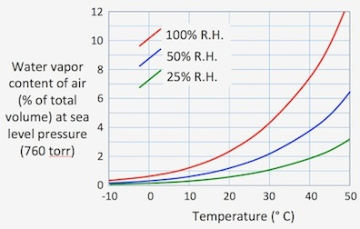
As can be seen in this diagram, the importance of water vapor compensation
is greatest at high ambient temperatures and high humidities. For
example, at a temperature of 30 °C, saturated air (100% R.H.) is about
4 percent water vapor by volume. That proportion increases to about
7 percent at 40 °C.
Keep in mind that these values are for a total barometric
pressure of 1 atmosphere. Since saturation vapor pressure at a given temperature is constant
regardless of the total pressure in the system, the fractional water
vapor content increases as total pressure decreases. For example,
if you are working at an altitude of 2000 meters (where atmospheric pressure
is roughly 590 torr), saturated air at 30 °C contains about 5.4% water
vapor by volume.
You can reduce or avoid these errors by using estimates of humidity,
or preferably measurements of humidity or dew point, to calculate
the volumetric fraction of incurrent gas comprised of water. This
figure should give you some idea of the need to compensate, given the temperature
and pressure conditions you work with.
Note that the temperature
and pressures of importance are those at the position of the flowmeter,
and not elsewhere in your system. Clearly, if you are working at fairly
low humidities and the temperature of your flowmeter is about 20 °C
or lower, the expected error is on the order of 1% or less, and probably
can be safely ignored. Even in fairly warm conditions (around 30 °C),
you can reduce the expected error to about 2% if you can guess relative
humidity within 50%.
Back to top
Water vapor content is usually measured as either percent relative
humidity or dew point temperature (in °C); some instruments can output vapor pressure as Pascals (or kiloPascals), or vapor density as g H2O vapor / m3 (same as mg H2O / L or µg H2O / mL).
The algorithms LabAnalyst uses to compute vapor density are derived from Properties
of Air, by Tracy, Welch, and Porter (1980; University of Wisconsin; you can find a pdf on the Web via Google Scholar).
In turn, these are based on the Smithsonian Meteorological Tables. For those interested, the formulae used are as follows:
• Vapor pressure (pw) at temperatures over liquid water (Smithsonian Tables, 1984, after Goff and Gratch, 1946):
Log10 pw = -7.90298 (373.16 T-1)
+ 5.02808 Log10(373.16 / T)
- 1.3816 10^-7 (10^11.344 (1-T / 373.16) -1)
+ 8.1328 10^-3 (10^-3.49149 (373.16 / T-1) -1)
+ Log10(1013.246)
with T in °K and pw in hPa
• Vapor pressure (pi) at temperatures below 0 °C (over ice; Smithsonian Tables, 1984):
Log10 pi = -9.09718 (273.16/T - 1)
- 3.56654 Log10(273.16/ T)
+ 0.876793 (1 - T/ 273.16)
+ Log10(6.1071)
with T in °K and pi in hPa
The Goff-Gratch equation (for air over liquid water) covers a temperature range of -50 °C to about 100 °C, but is mostly theoretical for very low temperatures. Accuracy is probably ±0.5% or better at temperatures between -20 and 70 °C.
|
• CAUTION: regardless of the accuracy of the equations, when working at cold and especially subzero temperatures it is technically very difficult to avoid inaccuracies due to condensation or freezing of water vapor on chamber walls, tubing, etc.
|
Back to top
Miscellaneous notes for respirometry:
SENSOR HUMIDITY COMPENSATION...
Normally, the preferred procedure is to scrub water
vapor from the sampled gas stream before measuring the concentrations of
O2 or CO2.
However, in some respirometry systems it is necessary or desirable to analyze
'wet' gas -- i.e., gas that contains some water vapor. For example,
you might want to make uninterrupted measurements over a very long period.
This introduces a potential problem: any desiccants used to scrub water
vapor may be exhausted before the measurements are completed (and you won't
be able to tell which data were obtained from dry gas and which were not).
By not removing water vapor at all, you can avoid that complication.
In order to accurately compute gas exchange rates from undried gas, it
is necessary to remove the dilution effect of water vapor in the gas stream
(which slightly reduces the concentration of O2
or CO2 in the gas analyzer). This
causes an underestimate (VCO2) or overestimate
(VO2) of 'true' gas exchange rates.
The resulting error is small if the temperature and relative humidity of
the measured gas are low, but increase rapidly as temperature and humidity
climb (see the figure in the section above on water
vapor correction showing the volumetric contribution of water vapor
at different temperatures and humidities). Low barometric pressure
increases the error still further.
You use several methods
for compensating for measurements on wet gas, but for all of them you must
provide information of the temperature and water content of the measured
gas stream. You can use recorded channels of relative humidity or
dew point, or provide a constant value. Similarly, you can use recorded
or constant values for temperature.
| Note that the sensor humidty routines in LabAnalyst compensate only
for the passive dilution effect of water vapor. They
cannot rectify any active interference with the sensor caused by water.
In other words, if a sensor detects water
vapor and 'confuses' it for the gas of interest (CO2 or O2),
there is no alternative to completely drying the gas stream prior to measurement.
Fortunately, most O2 and CO2 analyzers are relatively
immune to this problem. |
VO2 IN WATER... LabAnalyst (and other respirometry software) can calculate oxygen depletion curves or rates of O2
consumption of aquatic organisms, based on changes O2
concentration. The latter can be expressed in a variety of units: oxygen
partial pressure, i.e., pO2 (torr), percent
saturation of oxygen (zero to 100%), parts per million O2
(by mass), or mg O2/Liter (note that the
latter two units are identical).
- For closed-system measurements, LabAnalyst estimates the amount
of dissolved oxygen in the container at the start of measurements from
container volume, temperature, solute concentration, initial oxygen saturation,
and the partial pressure of O2 in the gas
phase (calculated from barometric pressure and the percentage of O2 in the gas mixture, and accounting for the
water vapor content of air at 100% RH).
- For open-system measurements, LabAnalyst estimates the amount
of dissolved oxygen in the water flux through the system from temperature,
solute concentration, initial oxygen saturation, and the partial pressure
of O2 in the gas phase (calculated from
barometric pressure and the percentage of O2
in the gas mixture, and accounting for the water vapor content of air at
100% RH)
- In absolute value mode, input data are assumed to be absolute
values, and VO2 is calculated by subtracting
them from baseline O2 concentration (i.e.,
the amount of O2 in the incurrent water
stream). Baseline O2 concentration
is computed from pressure, temperature, etc. as described above.
For example, if baseline O2 concentration
is 100% saturated, an oxygen saturation datum of 1% is assumed to mean
that 99% of the oxygen in the water stream has been consumed, and
VO2 is computed accordingly.
Back to top
Flow
rate measurement accuracy
In open-system respirometry, the most frequent source of error is probably
inaccuracies in measurement of gas flow rate. Aside from the required
correction to standard temperature and pressure (STP; 0 °C, 760 torr),
there are several common problems that can compromise accuracy:
An inaccurate
calibration of the flow measuring instrument. Most of
the various devices used to determine gas flow rates -- turbine-based meters,
rotometers ('ball in a tube' meters), mass flow meters, etc. -- require
periodic recalibration to maintain measurement accuracy. Even if
the initial factory calibration is dead on, there will be some drift over
time. Note that this is particularly true for mass flow devices (both
meters and controllers). After extensive use, the inevitable slight
buildup of airborne contaminants on the sensor will cause calibration drift.
There may also be some gas leakage or pressure change in the reference
portion of the sensor system.
- Recalibration can be done in a number of ways. You can
send your units back to the factory (at considerable cost in time and expense).
Alternately, you can check your meter against another meter with a calibration
you trust. Better yet, you can calibrate against a volume meter (like
a bubble meter or a good dry volume meter) that is relatively immune to
calibration drift (be sure to correct for STP during the calibration process).
One good do-it-yourself calibration method, particularly useful with dry-volume meters, is to evaporate a carefully weighed quantity of liquid nitrogen or dry ice (CO2) through the meter, and then check the cumulative volume against the expected volume of the evaporated gas (22.4 liters per mole, at STP). Be sure to account for effects of air pressure (if different from 760 Torr) and temperature (if different from the meter's calibration temperature).
Working
at unusual altitudes or pressures. Most flow meters are designed
and calibrated for a specific pressure range, usually fairly close to standard
sea-level air pressure. Usually, modest deviations from that standard
have little effect on accuracy, but if you go to high altitude (several
thousand meters) or work in strongly hyperbaric conditions, you should
check your calibration. Even some mass flow devices are not immune
to this problem (although they are supposed to compensate for the effects
of pressure changes).
- The accuracy of devices that measure gas volume changes directly (bubble
meters and dry volume meters) is generally unaffected by changes in working
pressure (at least within the range of pressures tolerated by most air-breathing
organisms).
Use of unusual
gas mixtures. Most flow devices are calibrated for a specific
gas (or gas mixture) and may require a correction factor when used with
different gases. Generally, for the kinds of devices used by people
doing respiromentry, the factory calibration is for pure nitrogen or for
air. As an example of the effects of non-standard gas mixtures, consider
'helox' (21% oxygen, 79% helium). This mix is often used by physiologists
to induce cold stress without risk of freezing injury, or to alter the
density, diffusion, and viscosity properties of the breathing mixture (it also makes
you talk in a squeaky voice if you breath it). If you use helox with
a mass flow device calibrated for nitrogen or air, the real flow rate for most
such units is about 33% greater than the indicated flow (this is because mass flow
devices measure flow from rates of heat transfer, and the heat transfer
properties of helium are quite different from those of nitrogen). However, I've seen considerably greater errors (2X - 3X) with some mass flow instruments.
- Devices that measure gas volume changes directly (bubble meters and
dry volume meters) are essentially unaffected by different gas mixtures.
Other common sources of error
An inaccurate
calibration of the gas analyzer. This is mainly an issue for humidity (water vapor) and CO2 analyzers; most modern oxygen analyzers rarely require span calibration -- in other words, a 1.0% change in O2 concentration is correctly read as a 1.0% change. They DO require periodic reference readings during measurements to account for drift, however. This means that even if you set the reference (unbreathed air) O2 concentration to read as the atmospheric value of 20.95%, subsequent reference checks will drift away from 20.95%.
For humidity and CO2 sensors, even if
the factory calibration is 'perfect', there will be some loss of span accuracy over
time -- more with some instruments, less with others. For both humidity and CO2 analyzers, the calibration procedure usually involves reading a gas with zero concentration of water vapor or CO2, adjusting the 'zero' setting on the analyzer, and then reading a gas with an independently known concentration of water or CO2 and adjusting the 'span' (or similar) setting. Refer to the analyzer manual for details. How often this needs to be done varies a lot between instruments but it should be a regular part of your laboratory routine, particularly with sensitive measurements. I'm often surprised when researchers contact me about some issue or other, and the conversation eventually gets around to analyzer calibration, and it becomes clear they had no idea it was necessary.
- With either water or CO2 analyzers, you need a non-zero 'span' (calibration) gas of known concentration of the gas of interest. For CO2, one typically purchases a cylinder (or two) of a very expensive precision gas mixture, with CO2 concentration close to but slightly higher than what you expect to be produced during your animal measurements. Of course, you're at the mercy of the vendor's procedures for the accuracy of the span gas concentration. It's also possible to start with pure 100% CO2 and CAREFULLY dilute it with CO2-free air to a known concentration (but I don't know anybody who does this).
- Calibrating humidity analyzers is often tricky. For one thing, capacitance-based sensors (which are common) are usually inaccurate at very high humidities (say, > 90%), so it isn't appropriate to use saturated gas (i.e., 100% RH). What's usually done is to measure water vapor (or humidity) over saturated salt solutions, which depress water vapor pressure compared to that over pure water. Different salt species give different saturation vapor pressures. It's challenging to mix these in a way that guarantees 'true' saturation, but it can be done with reasonable accuracy. A paper with some values for different solutes is Wexler & Hasegawa, Journal of Research of the National Bureau of Standards 53: 19-26 (1954); another is Winston & Bates, Ecology 41: 232-237 (1960). There are other relevant references if you search the literature; Properties of Air by Tracy, Welch, and Porter (University of Wisconsin and available on the Web via Google Scholar) has extensive tables for different solutes.
Leaks from the animal chamber or elsewhere in the plumbing. Depending on the construction of metabolism chambers, it may be difficult or impossible to make them completely leak-free. Often leaks don't affect measurement accuracy, as long as the amount of air (or other gas) entering the metabolism chamber is accurately known. For positive-pressure ('push') systems with upstream flowmeters, leakage downstream is often unimportant, as long as enough uncontaminated sample gas gets to the gas analyzers. For negative-pressure ('pull') systems, there cannot be leaks between the chamber, the flowmeter, and the device generating the suction. In either context, you need to make sure that your measured gas (either directly from the animal chamber gas outflow, or sub-sampled from that outflow) is NOT contaminated with room air. For example, if you sub-sample at 100 ml/min, but only 70 ml/min reaches the subsampling system, you've got problems. As a general rule, I always check for leaks by blocking tubing exiting the chamber and observing the flowmeter -- if there are no leaks, flow will drop to zero (of course, if the inflow is at high pressure, you may pop a tubing connector or burst the chamber...). I also often check the approximate metabolic rate against the expected metabolic rate (obtainable for most species from the metabolism calculator in the SPECIAL menu.
Back to top
| |
