The 'EXTERNAL DEVICE CONTROL' button
in the Display Setup window opens
a window for setting up computer-controlled switching of up to eight external
devices through UI-2's 'daughterboard' or the digital outputs of of the Datataker. If you are using an ADC-1,
the maximum number of switched devices is six, not eight.
NOTE: external device control is not available for the
Oscilloscope or Multichannel Oscilloscope modes.
CAUTION: external devices, unless they run at ~ 5 volts
with extremely small current drains (e.g., LED's), cannot
be driven directly.
Instead, switch devices through relays, preferably via opto-isolators.
The computer's device control lines require devices to be connected to
both power and ground. The voltage goes high when a device is switched
'on'.
| Warning: If you connect ANY
external device to a computer, the
responsibility for safe operation is yours, and yours alone. There are NO guarantees or warranties
associated with Warthog Systems, and I and the University of California
accept no liability of any kind for the use of this software. |
LabHelper
works quite well with the Sable
Systems respirometry multiplexers (these are 8-channel computer-controlled
valve banks), but there are a few special considerations.
Top of page
The timing and order of LabHelper's switching
modes alternate between sample and reference readings on single or multiple
channels. This is particularly useful for making measurements of metabolism
or evaporative water loss during flow-through respirometry. Five switching
modes are selected from the pop-up menu. In all modes, no more
than one of the eight possible devices is switched on at a given time
unless you select the '2 Device Groups'
option and your AD converter and the unit it is controlling can handle simultaneous operation of two devices. In the latter case, devices 1 through 4 are the first group
and devices 5 through 8 are the second group, and TWO sample devices are
switched on simultaneously (one from each group). There is one reference
device in the normal mode (selected from either group). If you have
selected two device groups, you must select one reference device from EACH
group. To use this option properly, you must have appropriate plumbing
AND make sure that at least one sample device is selected from BOTH Group
1 (devices 1-4) and Group 2 (devices 5-8). Note: the '2 Device Groups' option is not available with the Sable UI2, due to the way its output signals are coded.
 In this example, the
computer is controlling a cluster of 8 solenoid valves. Four of these
valves (2, 4, 6, and 8) are connected to different animal chambers.
The '2 Device Groups' option is used to split the 4 sample streams
into two groups, each of which is sampled -- ONE
AT A TIME -- by one channel of a 2-channel gas analyzer.
Note that for each 'bank' of valves, another input besides the two connected
to animal chambers must contain a stream of reference air (for example,
devices 1 and 5). Also, the best arrangement for most analyzers is
to 'sip' a small fraction of the excurrent air stream from each chamber.
The 'sippers' and gas scrubbers are not shown here for clarity. In this example, the
computer is controlling a cluster of 8 solenoid valves. Four of these
valves (2, 4, 6, and 8) are connected to different animal chambers.
The '2 Device Groups' option is used to split the 4 sample streams
into two groups, each of which is sampled -- ONE
AT A TIME -- by one channel of a 2-channel gas analyzer.
Note that for each 'bank' of valves, another input besides the two connected
to animal chambers must contain a stream of reference air (for example,
devices 1 and 5). Also, the best arrangement for most analyzers is
to 'sip' a small fraction of the excurrent air stream from each chamber.
The 'sippers' and gas scrubbers are not shown here for clarity.
- Note: the two groups are 1-3 and 4-6 when using the ADC-1.
In essence, the computer selects which single device in a group is connected
to a sensor at a given time -- either the reference device is connected
or one of several possible sample devices.
Top of page
Depending on hardware, LabHelper has two ways of coding the
digital signals to the external device. The two modes (selectable
with the switch code buttons in the upper right of the window) are:
one line per device (the Warthog default). Each of the
output lines in the I/O port is connected to a single device. When
the line goes high, the device it is connected to is switched on.
three-bit word. The external device must decode a signal
sent on three digital I/O lines (each line represents one bit of the three-bit
signal, yielding 8 possible values). NOTE: this coding mode does
not allow the '2 Device Groups' option. The Sable Systems multiplexer uses this control scheme (see the special
considerations page).
The
general switching pattern is shown in a simple graphic display at the right
of the window. Thick bars symbolize a channel being sampled; thin
bars represent reference periods; thin lines indicate times when a channel
is switched off (i.e., set to zero) while another channel in the same device
group is being read. Here is an example of a switching pattern:
Here, one device (#1) is in use for sampling data. Devices 4 is used for reference.
Top of page
The available switching modes are:
OFF (no device switching).
MANUAL (KEYBOARD) DEVICE SWITCHING. The
computer turns on a reference device at the start of a data collection run.
The reference device is switched off and a sampling device is switched on
when the '+' (plus-sign) key is struck. The reverse occurs when the
'-' (minus-sign or dash) key is struck. [Two reference or sampling
devices are switched on simultaneously if the 2 Device Group option has
been selected.]
If this mode is selected, the user must designate (1) a reference device
from the panel in the middle left of the screen, and (2) a sampling device
from the panel located at the bottom of the screen. Sampling devices
are assigned to particular data channel(s) by entering the appropriate device
number for the correct channel in the blue edit fields at the bottom left
of the screen (select device number 0 to leave a channel unassigned).
The 'Device Control Setup OK' button will be deselected until all
these conditions are met. Click the 'Check Configuration' button
to insure that LabHelper recognizes any changes.
KEYBOARD SWITCHING (WITH TIMER). This is similar to manual keyboard control, except that
the computer automatically switches back to sampling after a specified reference
interval has elapsed. Accordingly, you must specify a reference interval
in addition to the reference device and sampling device.
SWITCH TO REFERENCE AT START AND FINISH OF RUN. The computer turns on a reference device for a designated
period (the reference interval) at the start of a data collection run, then
switches to a sampling device for most of the rest of the run. At
the end of the run, the sampling device is switched off and the reference
device is switched on for a time equal to the reference interval.
[Two sampling devices are switched on simultaneously if the 2 Device Group
option has been selected.]
If this mode is selected, the user must designate (1) a reference device
from the panel in the middle left of the screen, (2) a sampling device from
the panel at the bottom of the screen, and (3) a reference interval >
zero, entered in the edit field in the upper right of the screen.
Note that only the FIRST sampling device selected will be switched, so select
1 only. Sampling devices are assigned to particular data channel(s)
by entering the appropriate device number for the correct channel in the
blue edit fields at the bottom left of the screen (select device number
0 to leave a channel unassigned). The 'Device Control Setup OK'
button will be deselected until all these conditions are met. Click
the 'Check Configuration' button to insure that LabHelper
recognizes any changes.
Top of page
PERIODIC REFERENCE, ONE OR MORE CHANNELS. LabHelper switches on the reference device(s) for
a reference interval at the beginning of a run, then steps sequentially
through a series of sample devices. The first sample device in the
sequence is switched on for a time equal to the sequence interval.
At the end of this interval, the reference devices are switched on for a
time equal to the reference interval. Then the next sample device
is turned on for a duration equal to the sequence interval, and the process
continues. When the last sample device has been selected and switched,
the cycle is repeated. This scenario continues until the data collection
run is complete.
The 'paradigm' for this mode is switching several different air streams
through a single set of gas analyzers. Note that whenever a sample
device is switched on, among the data channels which have sample devices
assigned to them only the channel(s) assigned to the currently selected
sample device(s) will record data. The other channels with assigned
sample devices will register zero volts. Thus an assigned channel
only records data when its assigned sample device is selected and operating.
All non-assigned channels record data at all times, and all channels (including
channels with assigned sample devices) record data during reference intervals.
[2 reference and 2 sample devices are switched on simultaneously if the
2-group option has been selected.]
If this mode is selected, the user must designate (1) reference device(s)
from the panel in the middle left of the screen, (2) one to seven sampling
devices from the panel at the bottom of the screen, (3) a reference interval
>0, and (4) a sequence interval > 0, which must be entered in the
edit field in the upper right of the screen. Sampling devices are
assigned to particular data channel(s) by entering the appropriate device
number for the correct channel in the blue edit fields at the bottom left
of the screen (select device number 0 to leave a channel unassigned).
The 'Device Control Setup OK' button will be dimmed (deselected)
until all these conditions are met. Click the 'Check Configuration'
button to make sure that LabHelper recognizes any changes.
Top of page
START & END, SEQUENTIAL FILES. This mode resembles the periodic references mode,
except that each external device is associated with a separate file
instead of a separate channel. A single channel (in the example
below, channel 1) is switched among several external devices. The
computer records one file from the first sample device (with references
at the beginning and end), then records another file from the second sample
device, and so forth until all assigned sample devices have been used and
the cycle repeats. In the example below, device 1 is the reference
device, and the sample devices are 2, 3, 5, and 7. When this mode
is selected, the autorepeat option is switched on by default.
If this mode is selected, the user must designate (1) a reference device
from the panel in the middle left of the screen, (2) at least one sampling
device from the panel at the bottom of the screen, and (3) a reference interval
> zero, entered in the edit field in the upper right of the screen.
The 'Device Control Setup OK' button will be deselected until all
these conditions are met. Click the 'Check Configuration' button
to insure that LabHelper recognizes any changes.
The bottom section of the device control window looks like this when
switched to sequential files mode. There is a select
button for each logical channel, and a numbered button for each possible
external device (6 for the ADC-1; 8 otherwise):
In this example, there
are eight logical channels and channel 3 is sequentially switched between
2 different external devices. Devices 1 and 4 are recorded
from on sequential files (another device is used for reference). The 'no references between channels' button is not selected, which means that a reference is taken at the start and end of each file. If this option was selected, one of the devices would have to serve as a reference (if a reference was needed).
- Note that when changing from this mode to other modes (and vice versa),
all device assignments are lost.
Top of page
In order to facilitate correct identification of a recorded file with
an assigned device,
 the computer will add a prefix to the "comments"
string saved with Warthog format files. The default prefix is "device
1", "device 2", etc, but you can assign any identifier you
wish (with a maximum length of 20 letters). This window -- opened
automatically whenever you access the External Devices window in
Sequential Files mode -- allows customization of the identifier strings.
You can also access this window from the Options
window. Example at right: the computer will add a prefix to the "comments"
string saved with Warthog format files. The default prefix is "device
1", "device 2", etc, but you can assign any identifier you
wish (with a maximum length of 20 letters). This window -- opened
automatically whenever you access the External Devices window in
Sequential Files mode -- allows customization of the identifier strings.
You can also access this window from the Options
window. Example at right:
During data acquisition in either Switch to Reference at Start and
Finish of Run mode or Periodic Reference mode, the operator can
manually switch between the reference device and the current sample device
by hitting the '-' or '+' keys, respectively.
When
the information in the EXTERNAL DEVICE CONTROL window is satisfactory,
click the 'Device Control Setup OK' button to return to the Display Setup window.
EXTRA ZERO LINKAGES... Zero linking is an option for periodic references, when one external device switches two logical channels. In this situation it is useful for the second channel to record zero when not 'connected' to the switched instrument. Zeroing helps to avoid confusion during analysis -- it's less likely that an incorrect assignment of data to animal will occur (the 'primary' channel automatically records zero when not 'connected').
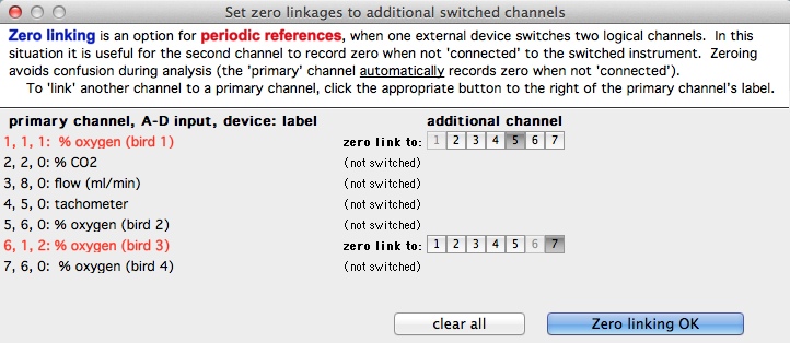
To 'link' another channel to a primary channel, click the appropriate button to the right of the primary channel's label; when everything is appropriate, click the 'OK' button.
|
 Warthog Systems LabHelper X