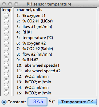
 If the data are in
units of relative humidity, you are asked to select a channel containing
humidity temperature data (as shown at right), or a constant temperature
for the RH sensor: If the data are in
units of relative humidity, you are asked to select a channel containing
humidity temperature data (as shown at right), or a constant temperature
for the RH sensor:
The software will compensate for temperature differences between the
humidity sensor and the flowmeter.
| One other effect of water vapor is (marginally) relevant if you use
a mass flow controller or mass flowmeter to handle your flow
rates. These devices ("MF's") determine rates of gas flow
by measuring rates of heat transfer. Unsurprisingly, the thermal properties
of water vapor are slightly different from those of dry air, so the addition
of water vapor to the air stream will have an effect on the calibration
accuracy of MF devices. However, under most imaginable respirometry
setups, this error is small and can safely be ignored. |
Back to top
Compensating for RQ: One of the many
troublesome complications in respirometry is that organisms seldom exchange
just one gas at a time: instead, they are simultaneously consuming
oxygen and producing CO2 (we'll leave
water out of this discussion because -- usually -- it can easily be scrubbed
from air streams prior to gas analysis). Since the ratio of CO2 produced / oxygen consumed (the Respiratory
Quotient, or RQ) is seldom exactly equal to 1.0, respiration causes
a net change in the total gas volume. As a result, gas concentrations
are affected. For example, consider a calculation of oxygen consumption:
If more oxygen is consumed than CO2 is produced,
the total gas volume is slightly reduced, which results in an increase in
the concentration of O2. This seemingly
trivial imbalance will influence exchange calculations and needs to be accounted
for (startlingly large errors can result if you don't do this correctly).
The necessary equations can be derived from simple algebra, but are tedious
in practice. Fortunately, equations for most respirometry systems
are built into LabAnalyst X (see below
for details).
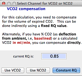 If you are calculating
oxygen consumption and you use a flow configuration that requires compensation
for CO2 production, you are asked if you
want to use a constant RQ value, or a previously computed channel
containing VCO2 (note that VCO2 must be in units of ml/min, or you may get
extremely inaccurate results),
or CO2 concentration data (in %
deflection from ambient CO2 concentration).
If you elect to use VCO2 or %CO2
, you will be asked to select the channel containing CO2 data. For maximal precision, be sure
to use the lag correction
function to synchronize the timing of oxygen and CO2
data (especially important if there are large short-term fluctuations
in gas concentrations). If you are calculating
oxygen consumption and you use a flow configuration that requires compensation
for CO2 production, you are asked if you
want to use a constant RQ value, or a previously computed channel
containing VCO2 (note that VCO2 must be in units of ml/min, or you may get
extremely inaccurate results),
or CO2 concentration data (in %
deflection from ambient CO2 concentration).
If you elect to use VCO2 or %CO2
, you will be asked to select the channel containing CO2 data. For maximal precision, be sure
to use the lag correction
function to synchronize the timing of oxygen and CO2
data (especially important if there are large short-term fluctuations
in gas concentrations).
Similarly, if you are calculating CO2 production,
you will always need to compensate for oxygen consumption (since animals rarely produce CO2 unless they are also consuming O2) and you
are asked if you want to use a constant RQ value, or oxygen concentration
data (in % deflection from ambient O2
concentration), or a previously computed channel containing VO2 in units of ml/min.
In most cases, use of a constant RQ will produce quite good accuracy.
Back to top
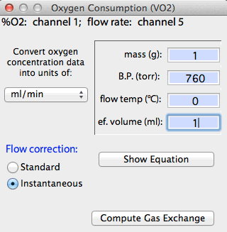
Units: As a last step, you need to
select the units for gas exchange. In the final window of the sequence,
you are presented with 4 or 5 edit fields containing mass, B.P., Ta, etc.
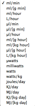
Adjust these as necessary. You can select from a variety of conversion
units in the pop-up menu (shown at right with ml/min selected).
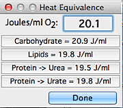 If you are calculating
VO2 or VCO2 in
watts or joules/time, you also need to set the correct value for heat
equivalency (an example for a VO2 calculation
is shown at right). The defaults (20.1 J/ml for VO2
and 25.0 J/ml for VCO2 ) are
reasonable for mixed diets. Theoretical heat values are shown for
pure carbohydrate, fat, and protein diets; see Gessaman and Nagy (1988,
Physiol. Zool. 61:507-513) for a discussion of gas exchange
conversion factors for metabolic calculations. If you are calculating
VO2 or VCO2 in
watts or joules/time, you also need to set the correct value for heat
equivalency (an example for a VO2 calculation
is shown at right). The defaults (20.1 J/ml for VO2
and 25.0 J/ml for VCO2 ) are
reasonable for mixed diets. Theoretical heat values are shown for
pure carbohydrate, fat, and protein diets; see Gessaman and Nagy (1988,
Physiol. Zool. 61:507-513) for a discussion of gas exchange
conversion factors for metabolic calculations.
You can click buttons to select appropriate values for carbohydrate,
lipid, or protein substrates. It is possible to directly enter your
own value into the edit field, however.
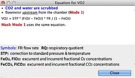
You can show the conversion equation by clicking the 'show equation'
button:
Back to top
Conversion equations
and options
Equations used for computing exchange rates are derived in part from
Depocas and Hart (1957; J. Appl. Physiol. 10:388-392),
Hill (1972, J. Appl. Physiol. 33:261-263) and Withers
(1977, J. Appl. Physiol. 42:120-123); others I derived
myself. The following symbols are used: FR = flow rate, V
= exchange rate for the gas in question (oxygen, CO2,
or water vapor), STP = factor for converting to standard conditions
of temperature and pressure, Fi = input fractional concentration,
Fe = excurrent fractional concentration, RQ = respiratory
quotient.
| Note: if you have already done the STP correction to the a
fixed flow rate or flow rate data in a separate channel -- for example,
if you measured flow with a mass flow controller with STP-corrected output,
or if you used the STP converter
in the OUTPUT menu and saved the
results-- make sure the temperature and pressure are set to 0 °C and
760 torr, respectively. |
| ONE MORE CAUTION: the algorithms
used here are appropriate for most -- BUT NOT ALL -- respirometry systems.
Check to make sure your system exactly matches the conditions outlined
below. |
For VO2,
the calculations depend on the position of the flowmeter and whether (and
where) water vapor and CO2 are absorbed.
Flow rate (FR) through the metabolism chamber is best measured upstream
from the chamber in most cases. If you need to humidify the air stream,
the best arrangement is to use an upstream flow meter, with the air dried
before it enters the flow meter and then re-humidified between the flow
meter and the chamber. For accurate calculations it is also necessary
to remove water vapor and helpful to scrub CO2 from
the air stream downstream from the animal chamber, before O2
content is measured.
If both CO2 and water are scrubbed
and the flowmeter is upstream from the chamber (Mode 1):
VO2 = STP * (FiO2 - FeO2) * FR / (1 - FeO2)
If both CO2 and water are scrubbed and the flowmeter is
downstream (Mode 3; Mask mode 1 uses the same equation after
correction of flowrate for incurrent water vapor content):
VO2 = STP * (FiO2 - FeO2) * FR / (1 - FiO2)
These are the simplest and most accurate ways to compute VO2 |
For some flow configurations you need to know RQ for accurate
calculation of VO2 , or you must have
a previously computed channel containing VCO2
in ml/min, or have data on %CO2 in
excurrent air (expressed as the difference from incurrent CO2 concentration). If the animal is
metabolizing carbohydrate, RQ is 1.0; if it metabolizes fat the RQ is about
0.7; if it metabolizes protein the RQ is about 0.8. Mixed diets yield
intermediate RQ. If you don't know RQ or diet, the potential
error is minimized if you use the default RQ of 0.85 (see Gessaman and Nagy
1988). Also, you should be aware that there are situations where the
CO2/O2 ratio
can exceed 1.0 (for example, if the
animal is depositing fat).
| CAUTION: If you are using the 'calculate from %CO2' or 'calculate from VCO2' modes, you need to exactly synchronize the oxygen and CO2 channels in time. This is especially important in serial configuration (first read CO2, then read O2) because the two analyzers are not 'looking' at the gas stream simultaneously (the lag correction option in the EDIT menu can usually fix this problem). Note that if your subject's metabolism is changing rapidly, this may not be possible even if you split your sample gas stream and read O2 and CO2 in parallel, as the response times of different gas analyzers are usually unequal. For example, the response time of a typical CO2 analyzer is seconds, while some O2 analyzers (like those from Applied Electrochemistry) respond in milliseconds.
|
In 'calculate from constant RQ'
mode:
If the flowmeter is upstream and CO2 is
not removed from the excurrent air stream at any point (Mode 2):
VO2 = STP * (FiO2 - FeO2) * FR / (1 - FeO2 * (1 - RQ))
If
the flowmeter is downstream and CO2 is not
scrubbed from the excurrent air stream prior to flow measurement
but IS removed prior to oxygen measurement (Mode 4 or Mask
Modes 2 and 4):
VO2 = STP * (FiO2 - FeO2) * FR / (1 - FiO2 + RQ * (FiO2 - FeO2))
If the flowmeter
is downstream and CO2 is not removed from
the excurrent air stream at any point (Mode 5 or Mask Modes 3
or 5):
VO2 = STP * (FiO2 - FeO2) * FR / (1 - FiO2 * (1 - RQ))
|
|
In 'calculate from VCO2' mode:
If the flowmeter is upstream and CO2
is not removed from the excurrent air stream at any point (Mode
2):
VO2 = STP * ((FiO2 - FeO2) * FR - FeO2* VCO2) / (1 - FeO2)
If the flowmeter
is downstream and CO2 is not scrubbed from
the excurrent air stream prior to flow measurement but IS
removed prior to oxygen measurement (Mode 4 or Mask Modes 2 and
4):
VO2 = STP * ((FiO2 - FeO2) * FR + VCO2 * (FeO2 - FiO2)) / (1 - FiO2)
If the flowmeter
is downstream and CO2 is not removed from
the excurrent air stream at any point (Mode 5 or Mask Modes 3
or 5):
VO2 = STP * ((FiO2 - FeO2) * FR - FiO2 * VCO2)/ (1 - FiO2) |
|
In 'calculate from % CO2' mode:
If the flowmeter is upstream and CO2
is not removed from the excurrent air stream at any point (Mode
2):
VO2 = STP * FR * ((FiO2 - FeO2) - FeO2* (FeCO2 - FiCO2)) / (1 - FeO2)
If the flowmeter
is downstream and CO2 is not scrubbed from
the excurrent air stream prior to flow measurement but IS
removed prior to oxygen measurement (Mode 4 or Mask Modes 2 and
4); note that this mode is sensitive to whether CO2
is scrubbed from the incurrent air stream:
VO2 = STP * FR * ((FiO2 - FeO2) - FiO2 * (FeCO2 - FiCO2) + FeO2 * FeCO2) / (1 - FiO2)
If the flowmeter
is downstream and CO2 is not removed from
the excurrent air stream at any point (Mode 5 or Mask Modes 3
or 5):
VO2 = STP * FR * ((FiO2 - FeO2) + FiO2 * (FiCO2 - FeCO2))/ (1 - FiO2)
|
Back to top
For VCO2,
you need to know RQ, or you must have data on oxygen content or consumption.
If you don't know RQ or diet, use the default RQ of 0.85, which usually
produces results with an error of <5%. Alternately, you can use
a previously-computed channel containing VO2
in ml/min, or have data on %O2 in
excurrent air (in difference from incurrent O2
concentration). The equations (which assume gas is
dry when FeCO2 is measured) are as follows:
| CAUTION: If you are using the 'calculate from %O2' or 'calculate from VO2' modes, you need to exactly synchronize the oxygen and CO2 channels in time. This is especially important in serial configuration (first read CO2, then read O2) because the two analyzers are not 'looking' at the gas stream simultaneously (the lag correction option in the EDIT menu can usually fix this problem). Note that if your subject's metabolism is changing rapidly, this may not be possible even if you split your sample gas stream and read O2 and CO2 in parallel, as the response times of different gas analyzers are usually unequal. For example, the response time of a typical CO2 analyzer is seconds, while some O2 analyzers (like those from Applied Electrochemistry) respond in milliseconds.
|
In 'calculate from constant RQ'
mode:
If the flowmeter is upstream from the chamber (Mode 1 or Mask Mode
1):
VCO2 = STP * (FeCO2 - FiCO2) * FR / (1 - FeCO2 * (1-(1/RQ)))
If
the flowmeter is downstream from the chamber and CO2
is not scrubbed prior to flow measurement (Mode 2):
VCO2 = STP * (FeCO2 - FiCO2) * FR / (1 - FiCO2 * (1-(1/RQ)))
If
the flowmeter is downstream and CO2 is scrubbed
prior to flow measurement (Mode 3 or Mask Mode 2):
VCO2 = STP * (FeCO2 - FiCO2) * FR / (1 - FeCO2 + FiCO2/RQ)
If you are
using a mask and the flowmeter is immediately downstream from the animal,
and water is scrubbed prior to CO2 measurement
(Mask Mode 3):
VCO2 = STP * (FeCO2 - FiCO2) * FR / (1 - FiCO2
* (1 + 1/RQ)) |
|
In 'calculate from VO2' mode:
If the flowmeter is upstream from the chamber (Mode 1):
VCO2 = STP * (FR * (FeCO2 - FiCO2) - FeCO2* VO2) / (1 - FeCO2)
If the flowmeter
is downstream from the chamber and CO2 is
not scrubbed prior to flow measurement (Mode 2 or Mask Mode 1 or
Mask Mode 3):
VCO2 = STP * (FR * (FeCO2 - FiCO2) - FiCO2* VO2) / (1 - FiCO2)
If the flowmeter
is downstream and CO2 is scrubbed
prior to flow measurement (Mode 3 or Mask Mode 2):
VCO2 = STP * (FR * (FeCO2 - FiCO2) - FeCO2* VO2) / (1 + FeCO2) |
|
In 'calculate from % O2' mode:
If the flowmeter is upstream from the chamber (Mode 1):
VCO2 = STP * FR * ((FeCO2 - FiCO2) - FeCO2* (FiO2 - FeO2)) / (1 - FeCO2)
If the flowmeter
is downstream from the chamber and CO2 is
not scrubbed prior to flow measurement (Mode 2 or Mask Mode 1 or
Mask Mode 3):
VCO2 = STP * FR * ((FeCO2 - FiCO2) + FiCO2* (FiO2 - FeO2)) / (1 + FiCO2)
If the flowmeter
is downstream and CO2 is scrubbed
prior to flow measurement (Mode 3 or Mask Mode 2):
VCO2 = STP * FR * ((FeCO2 - FiCO2) + FiCO2* (FiO2 - FeO2)) / (1 + FeCO2 - FiCO2) |
Back to top
For Evaporative Water Loss, the program assumes
there is no gas volume change between the part of the system where flow
rate is measured (whether upstream or downstream of the chamber) and the
point where water content is measured. The equation is:
EWL = (FeH2O - FiH2O) *STP * FR
with appropriate correction for whatever output units are desired.
This ignores any effects of VO2, VCO2, and changed water vapor content on flow rate
(in combination, these exchanges usually have a very minor effect on calculated
EWL). The equation is simple, but figuring out FiH2O and
FeH2O
from typical humidity data is not, because of the non-linear relationship
between temperature and the water content of a gas.
Water vapor content is usually measured as either percent relative
humidity or dew point temperature (in °C). Select the
appropriate units for your humidity sensor's output. In either case,
values must be converted into water vapor densities and then into
fractional concentrations. The equations for computing water vapor
density are arithmetically rather nasty (and therefore the speed of conversion
isn't as fast for some EWL calculations as for other kinds of gas exchange).
If you use % RH, the algorithms need to know the temperature of the humidity
sensor. You can either enter this directly or the value can be obtained
from a data channel. In the latter case, and for all analyses of dew
point data, vapor density calculations must be repeated for each sample
point. That slows the rate of conversion considerably, so a 'bar graph'
display is shown to indicate progress.
The algorithms used to compute vapor density are derived from Properties
of Air, by Tracy, Welch, and Porter (1980; University of Wisconsin).
Accuracy should be ±0.4% or better at temperatures between -20 and
70 °C. Note that in practice it is very difficult
or impossible to avoid error-inducing condensation or freezing of water
vapor when working at subzero temperatures.
Miscellaneous notes for gas exchange:
The 'instantaneous' correction helps compensate for the volumetric
washout characteristics of respirometry systems, using the 'Z' correction
approach modified for exponential washout kinetics (Bartholomew, Vleck,
and Vleck 1981, Journal of Experimental Biology 90, 17-32).
It works best in systems with large flow rates relative to effective volume.
In general, it is prudent to avoid this somewhat rude manipulation of data
if the system volume is large and the flow rate is low, unless the chamber
is very well stirred (as in a recirculating wind tunnel or a chamber with
mixing fans). In particular, be aware of the following:
| NOTE: Movements of animals
within chambers, relative to the position of input and output ports,
can introduce very ugly errors in instantaneous calculations because of
transient artifactual enrichments or rarifactions of local gas concentrations
that have nothing to do with real metabolic rates. |
Basically, the instantaneous conversion algorithm works from estimations
of how rapidly a gas concentration that has been transiently deflected
from a constant value will return to a state of zero deflection if no
other changes occur. Another way of putting it is as follows: if
an animal instantly changes its metabolism to a new steady-state value,
how long does it take for the excurrent gas concentrations to achieve their
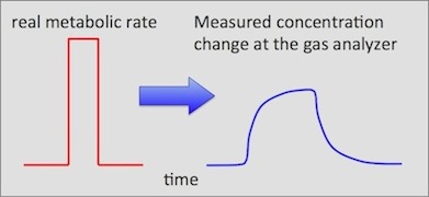
new steady state values? An instantaneous change in metabolism will
be detected at the gas analyzer as a gradual approach to new steady-states,
as shown schematically here:
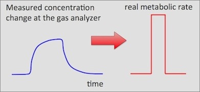
What the 'instantaneous' conversion does is back-calculate from the measured
concentration changes to approximate the real event:
For VO2 calculations the algorithm assumes
incurrent oxygen concentration is 20.95% and offset so as to read zero
at 20.95% oxygen. For carbon dioxide and water vapor it assumes
that incurrent concentrations are zero % (not offset). Calculations
will yield inaccurate results if these assumptions are violated. The
so-called effective volume (below) is necessary
for these calculations. It can be derived from a washout curve
for the system being used.
The response correction option in the TRANSFORMATIONS
routines (EDIT menu) can also adjust
for mixing problems and washout characteristics. It is based on an
unmodified Z-transform, and in some cases may be easier to use than the
instantaneous correction.
Back to top
SENSOR HUMIDITY COMPENSATION...
Normally, the preferred procedure is to scrub water
vapor from the sampled gas stream before measuring the concentrations of
O2 or CO2.
However, in some respirometry systems it is necessary or desirable to analyze
'wet' gas -- i.e., gas that contains some water vapor. For example,
you might want to make uninterrupted measurements over a very long period.
This introduces a potential problem: any desiccants used to scrub water
vapor may be exhausted before the measurements are completed (and you won't
be able to tell which data were obtained from dry gas and which were not).
By not removing water vapor at all, you can avoid that complication.
In order to accurately compute gas exchange rates from undried gas, it
is necessary to remove the dilution effect of water vapor in the gas stream
(which slightly reduces the concentration of O2
or CO2 in the gas analyzer). This
causes an underestimate (VCO2) or overestimate
(VO2) of 'true' gas exchange rates.
The resulting error is small if the temperature and relative humidity of
the measured gas are low, but increase rapidly as temperature and humidity
climb (see the figure in the section on water
vapor correction showing the volumetric contribution of water vapor
at different temperatures and humidities). Low barometric pressure
increases the error still further.
The Sensor humidity compensation option lets you use several methods
for compensating for measurements on wet gas, but for all of them you must
provide information of the temperature and water content of the measured
gas stream. You can use recorded channels of relative humidity or
dew point, or provide a constant value. Similarly, you can use recorded
or constant values for temperature. These are selected through a series
of windows. Note that some combinations require extensive vapor pressure
calculations for each data point, which slows the computation speed; in
these cases a progress bar is shown.
| Note that these routines compensate only
for the passive dilution effect of water vapor. They
cannot rectify any active interference with the sensor caused by water.
In other words, if a sensor detects water
vapor and 'confuses' it for the gas of interest (CO2 or O2),
there is no alternative to completely drying the gas stream prior to measurement.
Fortunately, most O2 and CO2 analyzers are relatively
immune to this problem. |
Back to top
VO2 IN WATER... This
routine will calculate oxygen depletion curves or rates of O2
consumption of acquatic organisms, based on changes O2
concentration. The latter can be expressed in a variety of units: oxygen
partial pressure, i.e., pO2 (torr), percent
saturation of oxygen (zero to 100%), parts per million O2
(by mass), or mg O2/Liter (note that the
latter two units are identical).
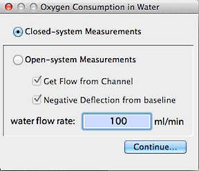
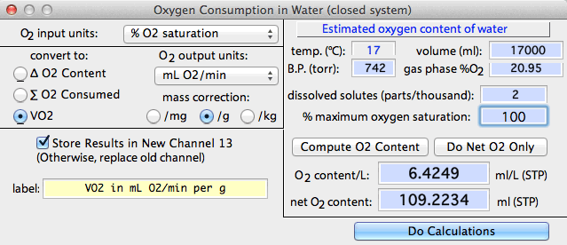
- For closed-system measurements, LabAnalyst estimates the amount
of dissolved oxygen in the container at the start of measurements from
container volume, temperature, solute concentration, initial oxygen saturation,
and the partial pressure of O2 in the gas
phase (calculated from barometric pressure and the percentage of O2 in the gas mixture, and accounting for the
water vapor content of air at 100% RH).
- For open-system measurements, LabAnalyst estimates the amount
of dissolved oxygen in the water flux through the system from temperature,
solute concentration, initial oxygen saturation, and the partial pressure
of O2 in the gas phase (calculated from
barometric pressure and the percentage of O2
in the gas mixture, and accounting for the water vapor content of air at
100% RH). Flow rates are obtained either from a channel or from keyboard
entry (you can also specify whether deflections in oxygen content are positive
or negative).
Most of these parameters can be edited with the EDIT
FILE DATA option, including flow rate, barometric pressure, temperature,
and container volume (= effective volume). Alternately, you can enter
your own O2 content data (dissolved oxygen
per unit volume) and click the 'net O2' button, or you can directly
enter net O2 content (total dissolved oxygen).
If there are less than 24 channels in the file, you can store results
in a new channel.
For closed-system measurements, there are three conversion options.
For any of these, you can generate absolute units or mass-specific units
(per mg, per g, or per kg). Note that all conversions are based
on the value shown in the 'net O2 content'
edit field. If you know that oxygen content differs from the
computed value in this edit field, you can enter your own value prior to
doing the conversion.
- cumulative oxygen content. This simply converts the input data
(% saturation, pO2, ppm, mg/L) into the
residual oxygen content of the container. You can select several
different output units, such as mL, microliters, mmoles, or micromoles.
The slope of this line over time (multiplied by -1) is the average rate
of oxygen consumption (VO2).
- total oxygen used. This option computes the cumulative
amount of oxygen used during the measurement, again with a choice of output
units. The slope of this line over time is the average rate of oxygen
consumption. As for the previous option, several choices of units
are available.
- oxygen consumption rate. This computes the rate of oxygen consumption
(VO2; in a choice of units) by taking the
point-to-point derivative of the relationship between oxygen use and time.
Note: unless the input data have been highly smoothed,
results may be noisy when averaged over short time intervals. However,
long-term VO2 averages should be quite
accurate, provided the O2 consumption
of the organism was stable over time.
Here is an example showing conversion into consumption rate (ml
O2 / [g . min]):
The Open-system (flow-through) routine will only compute oxygen
consumption rate, in your choice of units. You can use either
of two algorithms, selected with buttons in the initial window:
- In absolute value mode, input data are assumed to be absolute
values, and VO2 is calculated by subtracting
them from baseline O2 concentration (i.e.,
the amount of O2 in the incurrent water
stream). Baseline O2 concentration
is computed from pressure, temperature, etc. as described above.
For example, if baseline O2 concentration
is 100% saturated, an oxygen saturation datum of 1% is assumed to mean
that 99% of the oxygen in the water stream has been consumed, and
VO2 is computed accordingly.
- In change from ambient mode, baseline O2
concentration must be offset to zero (this should be done with the
BASELINE option prior
to oxygen calculations). In other words, an oxygen saturation datum
of 1% is assumed to be a 1% change from baseline percent, not an
absolute value of 1%.
Deflections in O2 concentration in the
excurrent stream may be either positive or negative (if the latter, click
the 'negative deflection' button in the initial window).
Back to top
 O2 HEAT EQUIVALENCE...
CO2 HEAT EQUIVALENCE... These options let
you set the caloric equivalent of one ml of oxygen or CO2;
the defaults are 20.1 joules/ml O2 and 25.0
joules/ml CO2. You can click buttons to
select appropriate values for carbohydrate, lipid, or protein substrates.
It is possible to directly enter your own value into the edit field, however.
This window appears automatically during gas exchange calculations if
you select output units of energy instead of gas volume.
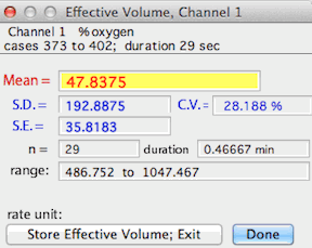
EFFECTIVE VOLUME... (Active channel only)
Uses a recorded gas washout curve to compute the 'effective volume' of an
open-circuit respirometry system. Effective volume is an expression
of the ratio of system volume to flow rate (it corresponds only approximately
to the real volume of chamber and plumbing). This routine bases
its calculations on washout rates of any gas, as long as the washout deflection
is measured as a change in % concentration and the equilibrium concentration
is offset to a 'baseline' of zero. This is done either during measurement
or with the baseline correction and transformations routines in LabAnalyst.
To generate a washout curve, set up the respirometry system as it is
normally used (but without an animal) at the flow rate used for measurements.
Make a recording of gas concentration, starting at equilibrium levels.
After establishing a baseline, deflect concentration by rapidly exhaling
into the incurrent flow upstream from the chamber (or quickly inject a bolus
of some gas with different concentration than reference gas). Continue
recording as gas concentration rapidly peaks, slowly declines, and eventually
returns to equilibrium concentration. Save the data. In LabAnalyst, correct the baseline to zero,
even for oxygen files (it will probably help to smooth
the data also). Mark a block in the washout curve as it returns to
equilibrium. Usually it is best to select from the middle of the washout
curve. Then select the effective volume option. LabAnalyst will request the flow rate and compute effective volume.
Back to top
Flow
rate measurement accuracy
In open-system respirometry, the most frequent source of error is probably
inaccuracies in measurement of gas flow rate. Aside from the required
correction to standard temperature and pressure (STP; 0 °C, 760 torr),
there are several common problems that can compromise accuracy:
An inaccurate
calibration of the flow measuring instrument. Most of
the various devices used to determine gas flow rates -- turbine-based meters,
rotometers ('ball in a tube' meters), mass flow meters, etc. -- require
periodic recalibration to maintain measurement accuracy. Even if
the initial factory calibration is dead on, there will be some drift over
time. Note that this is particularly true for mass flow devices (both
meters and controllers). After extensive use, the inevitable slight
buildup of airborne contaminants on the sensor will cause calibration drift.
There may also be some gas leakage or pressure change in the reference
portion of the sensor system.
- Recalibration can be done in a number of ways. You can
send your units back to the factory (at considerable cost in time and expense).
Alternately, you can check your meter against another meter with a calibration
you trust. Better yet, you can calibrate against a volume meter (like
a bubble meter or a good dry volume meter) that is relatively immune to
calibration drift (be sure to correct for STP during the calibration process).
One good do-it-yourself calibration method, particularly useful with dry-volume meters, is to evaporate a carefully weighed quantity of liquid nitrogen or dry ice (CO2) through the meter, and then checking the cumulative volume against the expected volume of the evaporated gas (22.4 liters per mole, at STP). Be sure to account for effects of air pressure (if different from 760 Torr) and temperature (if different from the meter's calibration temperature).
Working
at unusual altitudes or pressures. Most flow meters are designed
and calibrated for a specific pressure range, usually fairly close to standard
sea-level air pressure. Usually, modest deviations from that standard
have little effect on accuracy, but if you go to high altitude (several
thousand meters) or work in strongly hyperbaric conditions, you should
check your calibration. Even some mass flow devices are not immune
to this problem (although they are supposed to compensate for the effects
of pressure changes).
- The accuracy of devices that measure gas volume changes directly (bubble
meters and dry volume meters) is generally unaffected by changes in working
pressure (at least within the range of pressures tolerated by most air-breathing
organisms).
Use of unusual
gas mixtures. Most flow devices are calibrated for a specific
gas (or gas mixture) and may require a correction factor when used with
different gases. Generally, for the kinds of devices used by people
doing respiromentry, the factory calibration is for pure nitrogen or for
air. As an example of the effects of non-standard gas mixtures, consider
'helox' (21% oxygen, 79% helium). This mix is often used by physiologists
to induce cold stress without risk of freezing injury, or to alter the
diffusion and viscosity properties of the breathing mixture (it also makes
you talk in a squeaky voice if you breath it). If you use helox with
a mass flow device calibrated for nitrogen or air, the real flow rate
is about 33% greater than the indicated flow (this is because mass flow
devices measure flow from rates of heat transfer, and the heat transfer
properties of helium are quite different from those of nitrogen).
- Devices that measure gas volume changes directly (bubble meters and
dry volume meters) are essentially unaffected by different gas mixtures.
Back to top
|


 If the data are in
units of relative humidity, you are asked to select a channel containing
humidity temperature data (as shown at right), or a constant temperature
for the RH sensor:
