
| |
Hardware channel selection
|
|
This window sets the links between the 'logical' channel and a physical
connector to the analog-to-digital converter (UI2, DataTaker,
etc.). You can select any of the A to D channels that are available,
in any order; you may also assign a single hardware input to several logical
channels. The A to D INPUT window looks more-or-less like this example for the Sable UI2; the number of available inputs and other options depend on the specific A-D converter in use. 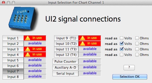
Here, four voltage inputs (including input 10, or T2, set at volts) and one temperature input (input 9; T1) have been selected. Several other inputs are available.
Special considerations:
Note that you can combine another ADAM module with a 4019: either another 4019, or the 4017. If you add a 4017, you will see 16 total inputs, but only the first 8 (from the 4019) have options for reading thermocouples -- the 4017 reads voltages only. Hardware connectors specific to the second ADAM module are indicated by an asterisk (*) on the 'Input' selection button. A number of Sable Systems instruments (and others) have serial ouputs; these send a fixed-format string of digital data directly to the computer, avoiding the need for an A-D converter. Therefore the channel selection window discussed above does not appear. Usually, several different variables are sent in a serial stream. LabHelper knows the 'signatures' of some Sable instruments (the first part of the string contains an instrument ID), and can parse the string into the appropriate variables, with channel labels.
Note that most Sable serial instruments update their serial strings only once or twice per second, so it's inadvisable to use this option at high sampling rates. |
| other links: |

 In this example, from the Sable
RH-100 humidty sensor, the device provides humidity as percent
relative humidity, dew point, and vapor pressure; it also shows
internal (cell) temperature. You need to pick one or more of these variables to
record.
In this example, from the Sable
RH-100 humidty sensor, the device provides humidity as percent
relative humidity, dew point, and vapor pressure; it also shows
internal (cell) temperature. You need to pick one or more of these variables to
record.