|
Before LabHelper
can acquire data, it must be given a sampling protocol which includes the following (some of these are optional):
recording mode
sample rates
matching logical to hardware channels
digital control of external devices
audible timer
alarm settings
|
the number of input channels
signal processing and voltage conversion
the duration of sampling
screen appearance options
analog output and feedback settings
X-Y plotting
| |
The initial input controls of LabHelper are be shown as a set of tabbed windows (below). You need to select one of three modes of operation:
- Chart
- Oscilloscope
- Oscilloscope plus chart
You can also load a 'setup file' with a complete pre-recorded
sampling protocol (setup files are stored from the OPTIONS
window). This will take you directly to the Acquisition parameters window.
 CHART
MODE gathers a fixed amount of data from 1 to 16 channels (up
to two million cases); the operator can intervene at any time to stop acquisition
before the maximum number of samples is obtained. Data
are plotted as separate line graphs for each channel.
Data are stored either under manual supervision (i.e., the operator selects
a new file name for each set of data) or automatically under the autorepeat
option. In autorepeat mode, the operator provides a 'root' file name
before data acquisition starts. Subsequently the program automatically
saves data whenever its buffer is full, appending sequential suffixes (1,
2, 3, 4, etc.) to the file root name for each save. Sample rates for
single channels can be as fast as several hundred per sec if you have a fast CPU and A-D converter,
but are slower if the number of channels
is large.
CHART
MODE gathers a fixed amount of data from 1 to 16 channels (up
to two million cases); the operator can intervene at any time to stop acquisition
before the maximum number of samples is obtained. Data
are plotted as separate line graphs for each channel.
Data are stored either under manual supervision (i.e., the operator selects
a new file name for each set of data) or automatically under the autorepeat
option. In autorepeat mode, the operator provides a 'root' file name
before data acquisition starts. Subsequently the program automatically
saves data whenever its buffer is full, appending sequential suffixes (1,
2, 3, 4, etc.) to the file root name for each save. Sample rates for
single channels can be as fast as several hundred per sec if you have a fast CPU and A-D converter,
but are slower if the number of channels
is large.
- The maximum 1-channel sampling rate is 3-5 samples/second with a slow DataTaker (DT50/500/600, about 10/second with ADAM modules, 20-50/second with a DataTaker DT800 (high-speed mode), > 200/second with a Sable UI2, and 62/second with a Sable UI3 (it should go faster but that's the maximum at this time).
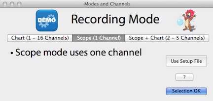 OSCILLOSCOPE
MODE works like a typical oscilloscope. Data from a single channel are plotted from left to right.
Whenever the next point would 'fall off' the right edge of the screen, plot
position is swapped to the left edge and each new point 'erases' the previous
point at that x-coordinate. The operator provides a 'root' file name
before data acquisition starts. Whenever the TAB key is struck, the
existing screenfull of data is saved under the root name plus a sequential
suffix number (see detailed description in the SETTING
UP section). An oscilloscope screen can contain up to 65,500
samples (about 16,000 samples in some sampling conditions). OSCILLOSCOPE
MODE works like a typical oscilloscope. Data from a single channel are plotted from left to right.
Whenever the next point would 'fall off' the right edge of the screen, plot
position is swapped to the left edge and each new point 'erases' the previous
point at that x-coordinate. The operator provides a 'root' file name
before data acquisition starts. Whenever the TAB key is struck, the
existing screenfull of data is saved under the root name plus a sequential
suffix number (see detailed description in the SETTING
UP section). An oscilloscope screen can contain up to 65,500
samples (about 16,000 samples in some sampling conditions).
- If you are using a slow DataTaker (DT50/500/600), the maximum sampling rate is
quite low, so
oscilloscope mode is NOT available.
- With the faster DataTaker DT800, modest scope sampling rates are possible but see this page to understand the limitations.
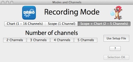 OSCILLOSCOPE
PLUS CHART MODE combines an oscilloscope channel with one to four chart
channels. Sampling rates for oscilloscope and chart channels
are usually quite different. Because this mode is a combination, it is also
a compromise: The oscilloscope channel cannot sample as fast as in 'pure'
oscilloscope mode, sample averaging is keyed to the sample rate of the oscilloscope
channel, and autorepeat is not available.
You should also be aware that if the chart channel sample rate is high,
chart timing may be affected by the time lost when oscilloscope screens
are saved to disk. OSCILLOSCOPE
PLUS CHART MODE combines an oscilloscope channel with one to four chart
channels. Sampling rates for oscilloscope and chart channels
are usually quite different. Because this mode is a combination, it is also
a compromise: The oscilloscope channel cannot sample as fast as in 'pure'
oscilloscope mode, sample averaging is keyed to the sample rate of the oscilloscope
channel, and autorepeat is not available.
You should also be aware that if the chart channel sample rate is high,
chart timing may be affected by the time lost when oscilloscope screens
are saved to disk.
- If you are using a slow DataTaker (DT50/500/600), the maximum sampling rate is
quite low, so
oscilloscope plus chart mode is NOT available.
- With the faster DataTaker DT800, modest scope sampling rates are possible but see this page to understand the limitations.
|
|
